설명
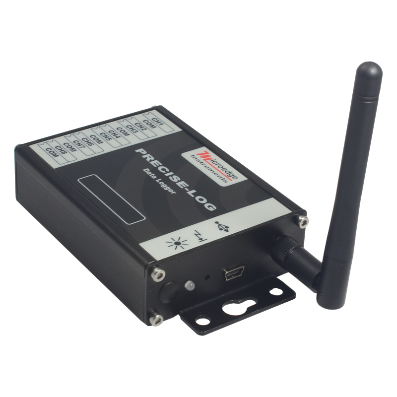
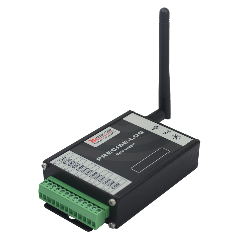
제품 : 무선 전류 데이터 로거
작성자 : MICROEDGE INSTRUMENTS (CANADA)
시리즈 : PRECISE-LOG
모델 : PL-CW
PL-CW는 8 채널, 배터리 전원, 독립형 및 WIFI 가능 전류 데이터 로거입니다. 로거는 8 개의 외부 전류 소스를 기록하고 8MB 메모리에 데이터를 저장합니다.
알루미늄 외함은 가혹한 산업 환경에서 탁월합니다.
내장 된 WIFI 모듈로 원격 데이터 모니터링 및 다운로드가 가능합니다.
16 비트 ADC는 정밀하고 정확한 측정이 중요한 과학 및 실험실 응용 분야에 적합합니다.
WIFI 적용 지역의 로거에 전원을 공급하고 컴퓨터에서 액세스하여 구성, 다운로드, 그래프보기 등을 수행하십시오 ...
풍모:
- 16 비트 아날로그-디지털 변환기
- 8MB 메모리 크기
- USB와 WIFI 통신 전송 속도가 115200bps 인 인터페이스
- 프로그래밍 가능한 입력 범위 (20mA, 50mA)
- 10 년 이상의 배터리 수명
- 구성, 다운로드, 플로팅, 분석 및 경보보고를위한 강력한 소프트웨어
- 광범위한 샘플링 간격 선택 (1 초 ~ 12 시간)
- 견고한 알루미늄 인클로저
Modbus
From July 15th, 2019, Modbus TCP protocol will be added to all PRECISE-LOG series of data loggers. A Modbus master/client can read one or more Input Registers and Holding Registers available in a PRECISE-LOG data logger through Modbus TCP communications. The below specifications list all supported commands and available registers PL-CW data logger supports:
Input Registers:
An Input Register stores a 16-bit integer for a channel’s real-time reading. To read one or more 16-bit Input register data, use function code 4.
| Register |
Description |
Type |
Range |
| 0 |
CH0 Value |
Unsigned Integer |
0 - 65535 |
| 1 |
CH1 Value |
Unsigned Integer |
0 - 65535 |
| 2 |
CH2 Value |
Unsigned Integer |
0 - 65535 |
| 3 |
CH3 Value |
Unsigned Integer |
0 - 65535 |
| 4 |
CH4 Value |
Unsigned Integer |
0 - 65535 |
| 5 |
CH5 Value |
Unsigned Integer |
0 - 65535 |
| 6 |
CH6 Value |
Unsigned Integer |
0 - 65535 |
| 7 |
CH7 Value |
Unsigned Integer |
0 - 65535 |
Example:
To read CH2, CH3 and CH4's real-time values, a Modbus master device sends in the following command:
| Data(HEX) |
Description |
Note |
| 0001 |
Transaction identifier |
Fixed 2-byte value |
| 0000 |
Protocol identifier |
Fixed 2-byte value |
| 0006 |
Length(6 bytes are followed) |
2-byte value |
| 01 |
The device address |
1-byte value, don't care |
| 04 |
Function Code (read Input Register) |
1-byte value |
| 0002 |
First register's address |
2-byte value |
| 0003 |
The number of required registers (read 3 registers 0002 to 0004) |
2-byte value |
Holding Registers:
A Holding Register stores a 16-bit integer indicating a setting for the data logger. To read one or more 16-bit Holding Register data, use function code 3.
| Register |
Description |
Type |
Range/Equation |
| 0 |
Sample Interval |
0: below 1 second
>=1: sample interval in second |
0 - 65535 seconds |
| 1 |
Device Operating Mode |
0: logging stopped
1: logger is logging data |
|
| X0 |
CHX-1 Type |
0: Range#0 (0 to 50 mA)
1: Range#1 (4 to 20 mA) |
|
| X1 |
CHX-1 Enabled |
0:disabled
1:enabled |
If a channel is disabled, the reading is unknown |
| X2 |
CHX-1 Equation |
0: Range#0 Current |
Range: 0 to 50 mA
Equation
O = 50 * I / 65535 |
| 1: Range#1 Current |
Range: 4 to 20 mA
Equation:
O = 16 * I / 65535 + 4 |
| 2: Linear |
O = (LRH – LRL) * I / 65535 + LRL
Where:
LRH is Linear Range high value
LRL is Linear Range low value
You can get those values from SiteView |
Where X = 1,2,3,4,5,6,7,8
O = Output, I = Input Register Value
Example:
To read CH3's equation, a Modbus master device sends in the following command:
| Data(HEX) |
Description |
Note |
| 0001 |
Transaction identifier |
Fixed 2-byte value |
| 0000 |
Protocol identifier |
Fixed 2-byte value |
| 0006 |
Length(6 bytes are followed) |
2-byte value |
| 01 |
The device address |
1-byte value, don't care |
| 03 |
Function Code (read Holding Register) |
1-byte value |
| 002A |
First register's address (42 is 2A in HEX) |
2-byte value |
| 0001 |
The number of required registers (read 1 registers 002A) |
2-byte value |
Note:
- Modbus feature was added to firmware version 2.05 or above.To upgrade a data logger's firmware please refer to this link: How can I upgrade logger firmware?
- The age of an Input Register data is based the data logger's sample interval.If the logger has stopped logging or the logger's sampling interval is slower than five seconds, a request of Input Register data will initiate the sampling process and the new data will be available upon the next request.